¶ Sera Genio520 OSM AOSP Software Programming guide
{{>toc}}
| Date | Revision | Description | Author |
|---|---|---|---|
| 20260604 | 1.0 | Initailize | PeterPan |
¶ Sera Genio520 SMARC SDK
This documentation provide MediaTek Genio 520 SMARC Sowftware.
The Genio520 SMARC software based on MediaTek Genio520, most software can reference from below URL.
https://mediatek.gitlab.io/genio/doc/android/index.html
This SDK based on the release of Mediatek IoT Android 15.
See https://mediatek.gitlab.io/genio/doc/android/sw/android/release-notes/iot-android-v15-release-note.html
¶ Abbreviations
- MTK: Abbreviation for MediaTek.
- OSM: Open Standard Module, an industry-standard specification for computer-on-modules.
- SMARC: Smart Mobility Architecture, a hardware standard for computer-on-modules.
- CABD: A PCB carrier board for SMARC/OSM modules designed by SERA Inc. for EVK production.
It provides physical interfaces such as USB, HDMI, Type-C, I2C, I2S, and UART. - CTBD: A converter board used only for OSM product lines.
It converts OSM pin definitions to SMARC pin definitions and connects to CABD.
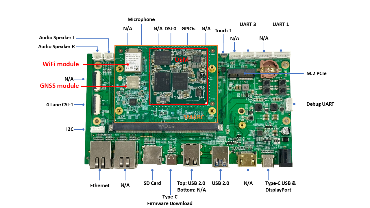
Below is OSM + CABD in this guide
¶ 1. Setup environment
¶ Linux Ubuntu 22.04 or docker.
¶ Android tool
Note - Due to CABD USB TYPE-C muxer schematic design, adb port was disabled. customer could redesign USB schematic circuit to enabled adb feature.
Android tool is for debug/console over USB
To install by apt
sudo apt-get install -y android-tools-adb android-tools-fastboot
or
sudo apt-get install -y adb fastboot
After installed, connect USB to device debug port and power on, then use adb scan available devices, like as.
src $ adb devices
List of devices attached
b0b3f759bb193aa8        device
Then we can connect to target device by adb shell
src $ adb shell
sh-5.1# uname -r
5.15.47-mtk+modified
sh-5.1#
¶ FlashTool
The Genio tools are a set of tools to flash, control or configure MediaTek boards, in particular the Genio evaluation kits.
It is also a public source in PyPi, so just run pip3 to install on host. and then setup USB
pip3 install -U genio-tools
See https://mediatek.gitlab.io/aiot/doc/aiot-dev-guide/master/sw/yocto/get-started/env-setup/flash-env-linux.html
After installed genio-flash, we could run genio-flash to flash/upload full image to target device later, even if the eMMC have no bootable loader code. Such as.
sudo genio-flash --load-dtbo display-dpoc.dtbo

You should download FlashTool from MTK offical support site.

Install in linux
After download FlashTool,
SP_Flash_Tool_Selector_exe_Linux_v1.2444.00.100 $ ./FlashToolSelector
launch it and select your SDK build target image folder to find flash.xml, for example
download_agent $ pwd
~/alps-release-u0.mp5-aiot-V7.67/out/target/product/aiot8391p2_64_bsp/merged/download_agent
download_agent $ ls
DA_BR.bin  flash.xml  flash.xsd

Then connect USB cable to TYPE-C Firmware Download port
- Push download key
- Turn on Power or push "reset key".
- If success we can see the processing status like below.
¶ 2. Download and build
make sure hard disk space size 2TB requirement.
To download G520/G720 OSM ASOP SDK, Customer require NDA License to fetch full source code.
Then download SERA OSM + CABD patches from SERA.
¶ Setup SDK
export LC_ALL=en_US.UTF-8
export LANG=en_US.UTF-8
export LANGUAGE=en_US.UTF-8
export MACHINE=genio-720-evk-ufs
For each session, make sure environment variables already setup.
After download by repo, Here two repositories, for example
alps-release-u0.mp5-aiot-V7.67
alps-release-v0.mp5-aiot-V4.74
alps-release-v0.mp5-aiot-V4.74 for system image
alps-release-u0.mp5-aiot-V7.67 for vendor image
cd to system sdk to initlize, in this case run below command with specific vendor folder by --vf
alps-release-v0.mp5-aiot-V4.74 $ vendor/mediatek/proprietary/scripts/releasetools/split_build_helper.py \
 full_aiot8391p2_64_bsp-userdebug \
 --vf /sera/AOSP_OSM/alps-release-u0.mp5-aiot-V7.67
Then if success, it pop on below messages, What we need to do next is just follow up commands to build image, the finally output should be located /sera/AOSP_OSM/alps-release-u0.mp5-aiot-V7.67/out/target/product/aiot8391p2_64_bsp/ and sub-folder merged is download information for FlashTool.
cd /sera/AOSP_OSM/alps-release-v0.mp5-aiot-V4.74 && source build/envsetup.sh && export OUT_DIR=out_sys && lunch sys_mssi_aiot_64_cn_armv82_wifi-next-userdebug && make sys_images
cd /sera/AOSP_OSM/alps-release-u0.mp5-aiot-V7.67 && source build/envsetup.sh && export OUT_DIR=out && lunch vnd_aiot8391p2_64_bsp-userdebug && make vnd_images krn_images
python /sera/AOSP_OSM/alps-release-v0.mp5-aiot-V4.74/out_sys/target/product/mssi_aiot_64_cn_armv82_wifi/images/split_build.py \
  --system-dir /sera/AOSP_OSM/alps-release-v0.mp5-aiot-V4.74/out_sys/target/product/mssi_aiot_64_cn_armv82_wifi/images \
  --vendor-dir /sera/AOSP_OSM/alps-release-u0.mp5-aiot-V7.67/out/target/product/aiot8391p2_64_bsp/images \
  --kernel-dir /sera/AOSP_OSM/alps-release-u0.mp5-aiot-V7.67/out/target/product/aiot8391p2_64_bsp/images \
  --output-dir /sera/AOSP_OSM/alps-release-u0.mp5-aiot-V7.67/out/target/product/aiot8391p2_64_bsp/merged
¶ 3. Development
In BSP, the Sera's Genio520/720 OSM/SMARC has many GPIOs, Some OSM PINs definition changed from MediaTek Genio520/720 in order to meet OSM/SMARC standard.
In most cases, it is done by modified dtb.
Kernel at alps-release-u0.mp5-aiot-V7.67/kernel/kernel_device_modules-6.1 and dtb at
alps-release-u0.mp5-aiot-V7.67/kernel/kernel_device_modules-6.1/arch/arm64/boot/dts/mediatek/aiot8391p2_64_bsp.dts
After modified kernel module or device tree. rebuild by by vnd_images krn_images then re-merge images. see below as example
cd /sera/AOSP_OSM/alps-release-u0.mp5-aiot-V7.67 && source build/envsetup.sh && export OUT_DIR=out && lunch vnd_aiot8391p2_64_bsp-userdebug && make vnd_images krn_images
python /sera/AOSP_OSM/alps-release-v0.mp5-aiot-V4.74/out_sys/target/product/mssi_aiot_64_cn_armv82_wifi/images/split_build.py \
  --system-dir /sera/AOSP_OSM/alps-release-v0.mp5-aiot-V4.74/out_sys/target/product/mssi_aiot_64_cn_armv82_wifi/images \
  --vendor-dir /sera/AOSP_OSM/alps-release-u0.mp5-aiot-V7.67/out/target/product/aiot8391p2_64_bsp/images \
  --kernel-dir /sera/AOSP_OSM/alps-release-u0.mp5-aiot-V7.67/out/target/product/aiot8391p2_64_bsp/images \
  --output-dir /sera/AOSP_OSM/alps-release-u0.mp5-aiot-V7.67/out/target/product/aiot8391p2_64_bsp/merged
¶ 4. Function validation
¶ GPIO
| Carrier GPIO Number | MT8391 EINT GPIO Number | Voltage |
|---|---|---|
| 1 | 5.0V | |
| 2 | 56 | 0-1.8V |
| 3 | 59 | Locked |
| 4 | 60 | 0-1.8V |
| 5 | 111 | 0-1.8V |
| 6 | 15 | 0-1.8V |
| 7 | 108 | 0-1.8V |
| 8 | 2 | Locked |
| 9 | 26 | Locked |
| 10 | 8 | 0-1.8V |
| 11 | 28 | 0-1.8V |
| 12 | GROUND | |
| 13 | 109 | 0-1.8V |
| 14 | 25 | 0-1.8V |
| 15 | 1.8V | |
| 16 | 3.3V |
Table show GPIO in Carrier Board maping to SOC GPIO number.
For example the GPIO13 in Carrier Board is controlled in 109 in SOC.
That is set
gpioset -c 0 109=1
will set CarrierBoard GPIO13.
For generic GPIOs, It can be validated using a set of GPIO tools.
gpioset and gpioget
For examples:
Set GPIO -c 0 60 to output high
gpioset 0 60=1
Set GPIO 173 to output low
gpioset -c 0 60=0
gpioget tool is to set GPIO as input and get status(high/low)
for example GPIO42 is GPIO input as download key, Default is high voltage.
gpioget -c 0 60
1
Now, while press download key and then get 0.
gpioget -c 0 60
0
¶ Type-C DisplayPort
Enabled as mirror mode by default in AOSP
¶ PCIe
By default PCI controller already built-in kernel image and no modify requirement.
In G520 OSM, PCIe support Gen2 by default, after insert PCI module to slot then power-on will see below.
root@genio-520-evk-ufs:~# lspci
00:00.0 PCI bridge: MEDIATEK Corp. Device 8189 (rev 01)
01:00.0 Network controller: Qualcomm Technologies, Inc WCN785x Wi-Fi 7(802.11be) 320MHz 2x2 [FastConnect 7800] (rev 01)
root@genio-520-evk-ufs:~# lspci -v
00:00.0 PCI bridge: MEDIATEK Corp. Device 8189 (rev 01) (prog-if 00 [Normal decode])
        Flags: bus master, fast devsel, latency 0, IRQ 299
        Memory at 30200000 (64-bit, non-prefetchable) [size=32K]
        Bus: primary=00, secondary=01, subordinate=01, sec-latency=0
        I/O behind bridge: [disabled] [32-bit]
        Memory behind bridge: 30000000-301fffff [size=2M] [32-bit]
        Prefetchable memory behind bridge: [disabled] [64-bit]
        Capabilities: [80] Express Root Port (Slot-), IntMsgNum 0
        Capabilities: [e0] MSI: Enable+ Count=1/32 Maskable+ 64bit+
        Capabilities: [f8] Power Management version 3
        Capabilities: [100] Vendor Specific Information: ID=1556 Rev=1 Len=008 <?>
        Capabilities: [110] L1 PM Substates
        Capabilities: [200] Advanced Error Reporting
        Kernel driver in use: pcieport

01:00.0 Network controller: Qualcomm Technologies, Inc WCN785x Wi-Fi 7(802.11be) 320MHz 2x2 [FastConnect 7800] (rev 01)
        Subsystem: Qualcomm Technologies, Inc WCN785x Wi-Fi 7(802.11be) 320MHz 2x2 [FastConnect 7800]
        Flags: fast devsel
        Memory at 30000000 (64-bit, non-prefetchable) [disabled] [size=2M]
        Capabilities: [40] Power Management version 3
        Capabilities: [50] MSI: Enable- Count=1/32 Maskable+ 64bit-
        Capabilities: [70] Express Endpoint, IntMsgNum 0
        Capabilities: [100] Advanced Error Reporting
        Capabilities: [148] Secondary PCI Express
        Capabilities: [158] Transaction Processing Hints
        Capabilities: [1e4] Latency Tolerance Reporting
        Capabilities: [1ec] L1 PM Substates
¶ Camera
Genio520 OSM support 4-lane x 2 in YUV, or RAW, The CABD designed as CSI 4-lane + CSI 2-Lane.
The OSM supports CSI 4-lane interfaces for IMX258 (RAW) and OV5640 (YUV), and a CSI 2-lane interface is reserved for future use.
¶ USB.
Overview of USB function in Genio520 specification.
The MediaTek MT8391 SuperSpeed Universal Serial Bus (SSUSB) module provides five ports.
- P0: Supports USB3.1 Gen1 peripheral role and USB2.0 dual-role capability.
- P1: Supports USB2.0 host only capability.
- P2: Supports USB2.0 host only capability.
- P3: Supports USB3.1 Gen1 host only and USB2.0 host only capability.
- P4: Supports USB2.0 host only capability.
Due to limtaion on CABD, OSM in CABD designed to
- P0: set to USB3.1 DisplayPort + USB2.0, no DualRole
- P1: set to USB2.0 host only capability.
- P2: set to USB2.0 host only capability.
- P3: set to USB2.0 host only capability.
root@genio-520-evk-ufs:~# lsusb
Bus 001 Device 001: ID 1d6b:0002 Linux Foundation 2.0 root hub
Bus 002 Device 001: ID 1d6b:0003 Linux Foundation 3.0 root hub
Bus 003 Device 001: ID 1d6b:0002 Linux Foundation 2.0 root hub
Bus 004 Device 001: ID 1d6b:0002 Linux Foundation 2.0 root hub
Bus 005 Device 001: ID 1d6b:0002 Linux Foundation 2.0 root hub
Bus 006 Device 001: ID 1d6b:0003 Linux Foundation 3.0 root hub
Bus 007 Device 001: ID 1d6b:0002 Linux Foundation 2.0 root hub
¶ MSDC
Already builtin kernel by default
After insert MSDC. use fdisk command as example below
sh-5.1# fdisk -l /dev/mmcblk1
Disk /dev/mmcblk1: 59.51 GiB, 63900221440 bytes, 124805120 sectors
Units: sectors of 1 * 512 = 512 bytes
Sector size (logical/physical): 512 bytes / 512 bytes
I/O size (minimum/optimal): 512 bytes / 512 bytes
Disklabel type: dos
Disk identifier: 0xb3085bb3

Device         Boot   Start       End   Sectors  Size Id Type
/dev/mmcblk1p1         8192   1056767   1048576  512M  c W95 FAT32 (LBA)
/dev/mmcblk1p2      1056768 124805119 123748352   59G 83 Linux
Note: SMARC Pin No. P30 - SDIO_WP(Write Protection) function is not implement.
¶ SDIO WiFi (optional)
G520/G720 OSM support onboad SDIO mt7921s WiFi
- Connect to AP.
> nmcli device wifi connect SeraAP ifname wlan0 password xxxxxxxx
Device 'wlan0' successfully activated with '4dcb781c-5e2b-4214-b51e-40ec1a988b51'.
- Get status and test performance
root@genio-520-evk:~# iw wlan0 link
Connected to cc:88:c7:a6:61:d2 (on wlan0)
        SSID: SeraAP
        freq: 5180
        RX: 183685918 bytes (179458 packets)
        TX: 1067852231 bytes (731871 packets)
        signal: -56 dBm
        rx bitrate: 351.0 MBit/s VHT-MCS 4 80MHz VHT-NSS 2
        tx bitrate: 6.0 MBit/s

        bss flags:      short-slot-time
        dtim period:    1
        beacon int:     100
root@genio-520-evk:~# iperf3 -c 172.16.10.6
Connecting to host 172.16.10.6, port 5201
[  5] local 172.16.30.67 port 46710 connected to 172.16.10.6 port 5201
[ ID] Interval           Transfer     Bitrate         Retr  Cwnd
[  5]   0.00-1.00   sec  45.9 MBytes   385 Mbits/sec    0   2.11 MBytes
[  5]   1.00-2.00   sec  50.0 MBytes   419 Mbits/sec    0   2.62 MBytes
[  5]   2.00-3.00   sec  47.5 MBytes   398 Mbits/sec    0   2.62 MBytes
[  5]   3.00-4.00   sec  52.5 MBytes   440 Mbits/sec    0   3.02 MBytes
[  5]   4.00-5.00   sec  50.0 MBytes   419 Mbits/sec    0   3.35 MBytes
[  5]   5.00-6.00   sec  42.5 MBytes   357 Mbits/sec    0   3.35 MBytes
[  5]   6.00-7.00   sec  51.2 MBytes   430 Mbits/sec    0   3.35 MBytes
[  5]   7.00-8.00   sec  48.8 MBytes   409 Mbits/sec    0   3.55 MBytes
[  5]   8.00-9.00   sec  51.2 MBytes   430 Mbits/sec    0   3.55 MBytes
[  5]   9.00-10.00  sec  51.2 MBytes   430 Mbits/sec    0   3.55 MBytes
- - - - - - - - - - - - - - - - - - - - - - - - -
[ ID] Interval           Transfer     Bitrate         Retr
[  5]   0.00-10.00  sec   491 MBytes   412 Mbits/sec    0             sender
[  5]   0.00-10.01  sec   490 MBytes   410 Mbits/sec                  receiver
¶ SPI
There are 2 master SPI devices on Genio 520/720-EVK
The device tree definition enabled SPI0,SPIM1 need customize/reasigned pins by user.
Those pins are connect to TestPoint(TP) in CABD.
| (EINT)Ball Name(Ball Number) | Net Name of EVK(EVK_schematic) | Net Name of OSM (OSM-LF_schematic) | OSM-SMARC board (OSM_SMARC) | Carrier board (Mainboard) |
|---|---|---|---|---|
| (70)SPIM0_CLK(AF15) | SPIM0_CLK | (AF15)SPI_A_SCK(U16) | (U16)SPI_A_SCK/SPI0_CK(P44) | (P44)SPI0_CK/TP25 |
| (69)SPIM0_CSB(AG15) | SPIM0_CSB | (AG15) SPI_A_CS0#(Y15) | (Y15)SPI_A_CS0/SPI0_CS#(P43) | (P43)SPI0_CS/TP24 |
| (71)SPIM0_MOSI(AD15) | SPIM0_MOSI | (AD15)SPI_A_SDI(U15) | (U15)SPI_A_SDI/SPI0_DIN(P45) | (P45)SPI0_DIN/TP26 |
| (72)SPIM0_MISO(AE15) | SPIM0_MISO | (AE15)SPI_A_SDO(V15) | (V15)SPI_A_SDO/SPI0_DO(P46) | (P46)SPI0_DO/TP27 |
| (74)SPIM1_CLK(AJ15) | SPIM1_CLK | (AJ15)SPI_B_SCK(Y21) | (Y21)SPI_B_SCK/SPIM2_CLK(P56) | (P56)SPI2_CK/TP30 |
| (73)SPIM1_CSB(AH15) | SPIM1_CSB | (AH15) SPI_B_CS0#(AA23) | (AA23)SPI_B_CS0#/SPIM2_CSB(P54) | (P54)SPI2_CS/TP29 |
| (75)SPIM1_MOSI(AH13) | SPIM1_MOSI | (AH13)SPI_B_SDI(Y22) | (Y22)SPI_B_SDI/SPIM2_MISO(P57) | (P57)SPI2_MISO/TP31 |
| (76)SPIM1_MISO(AH14) | SPIM1_MISO | (AH14)SPI_B_SDO(Y23) | (Y23)SPI_B_SDO/SPIM2_MOSI(P58) | (P58)SPI2_MOSI/TP32 |
¶ I2S
G520 OSM use I2SIN0 in capture, I2SOUT1 in playback.
Below shows the I2S signal path from MT8391 (OSM) to ES8388 (Mainboard) through OSM-SMARC board, and the pin mapping of each pin in the path.
| (EINT)Ball Name(Ball Number) | Net Name of EVK(EVK_schematic) | Net Name of OSM (OSM-LF_schematic) | OSM-SMARC board (OSM_SMARC) | Carrier board (Mainboard) |
|---|---|---|---|---|
| (103)I2S0_MCLK(AJ7) | I2SIN0_MCK | (AJ7)<-I2SIN0_MCK(I2SOUT0_MCK)/I2S_MCLK->(V18) | (V18)I2S_MCLK/AUDIO_MCK->(S38) | (S38)AUDIO_MCK/I2S0_MCLK |
| (104)I2SIN0_BCK(AH8) | I2SIN0_BCK | (AH8)<-I2SIN0_BCK/I2S_A_BITCLK->(W20) | (W20)<-I2S_A_BITCLK/I2S0_CK->(S42) | (S42)I2S0_CK/I2S0_SCLK_TX |
| (138)GBE_AUX_PPS1(AE19) | I2SOUT0_DO | (AE19)I2S_B_DATA_OUT(W19) | (W19)I2S_B_DATA_OUT/I2S2_SDOUT(S51) | (51)I2SO2_D0/I2S2_SDOUT |
| (105)I2SIN0_LRCK(AH7) | I2SIN0_LRCK | (AH7) I2SIN0_LRCK/I2S_A_LRCLK->(W18) | (W18)I2S_A_LRCLK/I2S0_LRCK->(S39) | (S39)I2S0_LRCK/I2S0_LRCK_TX |
| (106)I2S0_SDI0(AH9) | I2SIN0_DI | (AH9)<- I2SIN0_DI/I2S_A_DATA_IN->(V21) | (V21)I2S_A_DATA_IN/I2S0_SDIN->(S41) | (S41)I2S0_SDIN/I2S0_SDI0 |
| (25)DSI_LCM_RST(AC32) | DSI_LCM_RST | (AC32)DSI_LCM_RST/ GPIO_D_6->(Y32) | (Y32)GPIO25/GPIO_D_6/GPIO13->(S123) | (S123)GPIO13/MT8370_GPIO13/SPK_CTL_H |
In OSM+CABD project, OSM uses only 5 I2S signals: MCK, BCK, LRCK, DO, and DI. The MCK, BCK, and LRCK signals are shared between playback and capture. For capture, 4 pins (103, 104, 105, 106) are used for MCK, BCK, LRCK, and DI respectively; for playback, 4 pins (103, 104, 105, 138) are used for MCK, BCK, LRCK, and DO respectively.
Where EINT138(GBE_AUX_PPS1) is used as I2S_B_DATA_OUT for playback,belong to I2SOUT1 rather than I2SOUT0, and the I2SOUT1 is not used in Genio520 EVK
See MT8391/Genio520 audio subsystem information: https://mediatek.gitlab.io/aiot/doc/aiot-dev-guide/master/sw/yocto/porting-guide/audio/audio-porting-g720-i2s.html
| Interface Name | Block on AFE Route Diagram | Front End DAI Name | Back End DAI Name |
|---|---|---|---|
| I2SOUT0 | eTDM out0 | DL1 | I2SOUT0_BE |
| I2SOUT1 | eTDM out1 | DL3 | I2SOUT1_BE |
| I2SIN0 | eTDM in0 | UL1 | I2SIN0_BE |
| I2SIN1 | eTDM in1 | UL3 | I2SIN1_BE |
¶ UART
J24 in CABD is /dev/ttyS0 for debug
J20 in CABD is /dev/ttyS1 4 wires.
J22 in CABD is /dev/ttyS3 2 wires.
J21 in CABD no function.
| (EINT)Ball Name(Ball Number) | Net Name of EVK(EVK_schematic) | Net Name of OSM (OSM-LF_schematic) | OSM-SMARC board (OSM_SMARC) | Carrier board (Mainboard) UART |
|---|---|---|---|---|
| (33)UART1_TXD(AH12) | UART1_TXD | (AH12)UART_A_TX->(B13) | (B13)UART_A_TX/SER0_TXD->(P129) | (P129)SER0_TX/SER0_TXD/CON_SER0_TXD->(J20) |
| (34)UART1_RXD(AJ12) | UART1_RXD | (AJ12)UART_A_RX->(A14) | (A14)UART_A_RX/SER0_RXD->(P130) | (P130)SER0_RX/SER0_RXD/CON_SER0_RXD->(J20) |
| (36)UART2_RXD(AF11) | UART2_RXD | (AF11)UART_A_RTS->(C13) | (C13)UART_A_RTS/SER0_RTS->(P131) | (P131)SER0_RTS#/SER0_RTS/CON_SER0_RTS->(J20) |
| (35)UART2_TXD(AG11) | UART2_TXD | (AG11)UART_A_CTS->(C14) | (C14)UART_A_CTS/SER0_CTS->(P132) | (P132)SER0_CTS#/SER0_CTS/CON_SER0_CTS->(J20) |
| (31)UART0_TXD(AH11) | UART0_TXD | (AH11)UART_CON_TX->(D23) | (D23)UART_CON_TX/SER1_TX->(P134) | (P134)UART0_TXD/SER1_TX/UART0_TXD/SER1_TXD_Debug(J24) |
| (32)UART0_RXD(AH10) | UART0_RXD | (AH10)UART_CON_RX->(D22) | (D22)UART_CON_RX/SER1_RX->(P135) | (P135)UART0_RXD/SER1_RX/UART0_RXD/SER1_RXD_Debug(J24) |
| --- | --- | --- | --- | --- |
| (None) | NC | NC SoC pin | NC | (P136)UART2_TXD/SER2_TX/UART2_TXD/CON_SER2_TXD(J21) |
| (None) | NC | NC SoC pin | NC | (P137)UART2_RXD/SER2_RX/UART2_RXD/CON_SER2_RXD(J21) |
| (None) | NC | NC SoC pin | NC | (P138)UART2_RTS/SER2_RTS#/UART2_RTS/CON_SER2_RTS(J21) |
| (None) | NC | NC SoC pin | NC | (P139)UART2_CTS/SER2_CTX#/UART2_CTS/CON_SER2_CTS(J21) |
| --- | --- | --- | --- | --- |
| (37)UART3_TXD(AD11) | UART3_TXD | (AD11)UART_B_TX->(D13) | (D13)UART_B_TX/SER3_TX->(P140) | (P140)UART3_TXD/SER3_TX/UART3_TXD(J22) |
| (38)UART3_RXD(AE11) | UART3_RXD | (AE11)UART_B_RX->(D14) | (D14)UART_B_RX/SER3_RX->(P141) | (P141)UART3_RXD/SER3_RX/UART3_RXD(J22) |
Here One of UART used to GNSS
| (EINT)Ball Name(Ball Number) | Net Name of EVK(EVK_schematic) | Net Name of OSM (OSM-LF_schematic) | OSM-SMARC board (OSM_SMARC) | Carrier board (Mainboard) UART |
|---|---|---|---|---|
| (18)CMMPDN0(AC3) | I2SIN1_MCK | (AC3)UART_C_TX->(B23) | (B23)UART_C_TX/SER2_TX->GNSS_RYS3520 | NA |
| (19)CMMRST0(AC4) | I2SIN1_BCK | (AC4)UART_C_RX->(A22) | (A22)UART_C_RX/SER2_RX->GNSS_RYS3520 | NA |
¶ GNSS
Here an GNSS module on CTBD connected by UART2.
Here is basic setup.
- Configure ttyS2
stty -F /dev/ttyS2 -crtscts
stty -F /dev/ttyS2 115200
stty -F /dev/ttyS2 -a
stty -F /dev/ttyS2 115200 raw -echo -echoe -echok
- Test
timeout 1 cat /dev/ttyS2 &
echo -ne '$PAIR051*3E\r\n' > /dev/ttyS2
Then will show below ascii format from GNSS.
$GNGGA,001710.012,,,,,0,0,,,M,,M,,*52
$GNGLL,,,,,001710.012,V,N*60
$GNGSA,A,1,,,,,,,,,,,,,,,,1*1D
$GNGSA,A,1,,,,,,,,,,,,,,,,2*1E
$GNGSA,A,1,,,,,,,,,,,,,,,,3*1F
$GNGSA,A,1,,,,,,,,,,,,,,,,4*18
$GPGSV,1,1,00,1*64
$GLGSV,1,1,00,1*78
$GAGSV,1,1,00,7*73
$GBGSV,1,1,00,1*76
$GNRMC,001710.012,V,,,,,,,060180,,,N,V*22
$GNVTG,,T,,M,,N,,K,N*32
$GNZDA,001710.012,06,01,1980,,*4B
¶ I2C
It is free to use I2C tool testing I2C, for example
~ $ adb shell
sh-5.1# # i2cdetect  -y 6
     0  1  2  3  4  5  6  7  8  9  a  b  c  d  e  f
00:          -- -- -- -- -- -- -- -- -- -- -- -- --
10: -- -- -- -- 14 -- -- -- -- -- -- -- -- -- -- --
20: -- -- -- -- -- -- -- -- -- -- -- -- -- -- -- --
30: -- -- -- -- -- -- -- -- -- -- -- -- -- -- -- --
40: -- -- -- -- -- -- -- -- UU -- -- -- -- -- -- --
50: -- -- -- -- -- -- -- -- -- -- -- -- -- UU -- --
60: -- -- -- -- -- -- -- -- -- -- -- -- -- -- -- --
70: -- -- -- -- -- -- -- --
List available I2C bus and ball name in OSM+CABD.
| G520(PIO) | G520_OSM | OSM-SMARC | CARRIER | Description | Status |
|---|---|---|---|---|---|
| I2C0 PiHAT | AG7,AE7 (AA15,AA16) | (AA15,AA16) (P121,P122) | P121,P122 ES8323(0x11) | OK | |
| I2C1 PiHAT | AF7,AD7 (AA20,AA21) | (AA20,AA21) (S48,S49) | (S48,S49) RT1715WSC(0x4E) | OK | |
| I2C2 Current Monitor | GPIO4,GPIO5 (P112/P113) | (P112/P113) | GPIO4,GPIO5 | NA | |
| I2C3 NA | PCIe Port (AG17,AE17) | NA | NA | G520 I2C in OSM used in PCIe, no I2C function | NA |
| I2C4 Charger | NA | NA | NA | NA | |
| I2C5 PD(RT1715WSC) | NA | NA | NA | NA | |
| I2C6 MIPI TP/SBU MUX | AD16,AE16 (W32,W33) | (W32,W33) GPIO (S139,S140) | (S139,S140) IT5205@0x48,RS014YQ | 0x5D touch1 and IT5205 mux | OK |
| I2C7 CAM0 | CAM_A | SCL7 (C4,C3) (S1,S2) | (S1,S2)CSI1 | OV5640 | OK |
| I2C8 CAM1 | CAM_B (G4,G3) | (AB25,AB26) CAM_B_SC (S4,S5) | (S4,S5) | (Carrier Board CSI0A) | NA |
¶ OSM limitation.
OSM in CABD(Carrier Board) have some limitation
- Due to CABD circuit, Only CSI1 4-Lanes compatible in OSM. and Linux driver is camera-ov5640-csi1-osm.dtbo. RAW sensor on ready.
- Due to CABD circuit, Dual-Role Type-C USB3.0 not support in CABD, and ADB debug mode was disabled by SDK.
- Audio in ES8323 is POC, in developing